The source code and some artwork files are available from my local download or from github.com/larsi-org/MAME-Interface
The Button Layout
I decided to build only a single player controller with just one joystick and a few buttons. After a whole day of on-line "research" I decided to have 6 play buttons (instead of 8), 2 Player1 control buttons, and 4 system control buttons. I use the following mapping:
| # | Function | Keyboard Code | Teensy Pin | Teensy Port |
|---|---|---|---|---|
1 | Player1 Up | Up | 0 | PB0 |
2 | Player1 Down | Down | 1 | PB1 |
3 | Player1 Left | Left | 2 | PB2 |
4 | Player1 Right | Right | 3 | PB3 |
5 | Player1 Button1 | L-Ctrl | 4 | PB7 |
6 | Player1 Button2 | L-Alt | 5 | PD0 |
7 | Player1 Button3 | Space | 6 | PD1 |
8 | Player1 Button4 | L-Shift | 7 | PD2 |
9 | Player1 Button5 | Z | 12 | PD7 |
10 | Player1 Button6 | X | 13 | PB4 |
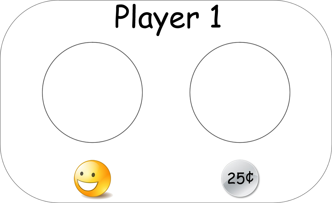
11 | Player1 Start | 1 | 14 | PB5 |
12 | Player1 Coin | 5 | 15 | PB6 |
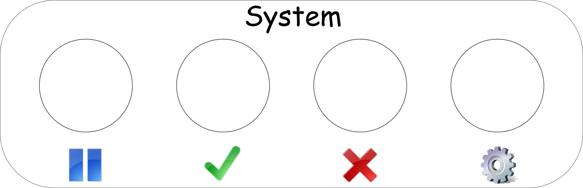
13 | Pause | P | 16 | PF7 |
14 | UI Select | Enter | 17 | PF6 |
15 | UI Cancel | Esc | 18 | PF5 |
16 | Config Menu | Tab | 19 | PF4 |
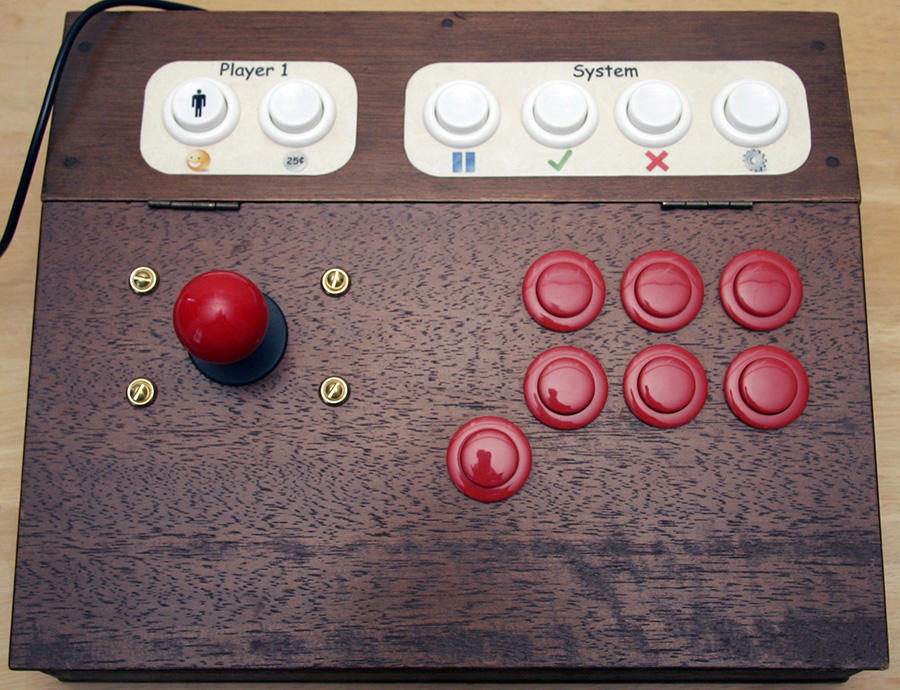
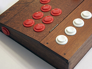
That means I have a total of 16 inputs. I want to use some buttons multiple times - Button1 is used again under the 6 buttons (as a fake 7th button for NeoGeo games) and Button1 and Button2 are also on the left and right for Pinball games. So I need a total 9 play buttons which are all red. The control buttons are all white with the exception of the Player1 Start button, which has a special symbol.
There are many great sites where you can buy all kinds of buttons and joysticks, like Ultimarc, ArcadeShop.de, Suzo-Happ, or X-Arcade. I decided to use SparkFun's Short Handle Arcade Joystick and Suzo-Happ's Competition Pushbutton for the play buttons and the regular Pushbutton for the control buttons.
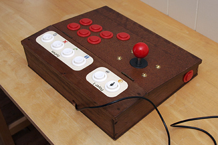
The Controller
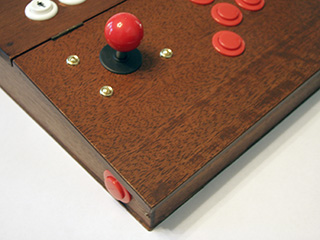
The next step was to find an enclosure for the button, the joystick, and the electronics. I wanted something better than a plastic box, maybe something a little more steampunk... After looking around I settled for getting a "Vintage Wooden Lap Desk" on eBay. The slightly slanted surface is perfect. I applied my layout by printing it out and marking the center holes with a pushpin. After this I started with a small drill and went up a few steps until I had drilled all holes with a ¼" drill. The last step was to drill with a 1 1/8 " drill, which was more difficult than I anticipated. I had to recharge the drill a few times and unfortunately the holes were not as clean as I had hoped. Basically I had scratched the top surface badly.
 |
 |
 |
To hide my mistakes from the last drilling and to label the button I decided to decoupage some paper on top of the wood (check out the download section). I had to cleanup the wooden surface and glue the mask over it. The next day I sealed the surface and I repeated the sealing process the next two days.
 |
 |
The Controller Board
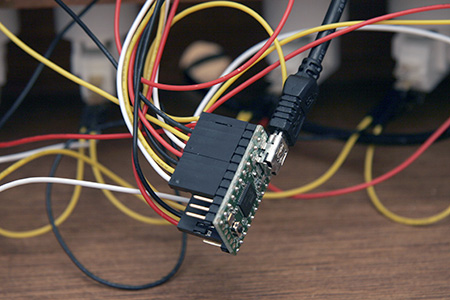
I thought about just using the popular I-PAC 2 or the easy to use Arcade Controller. After reading about the V-USB project and related sub projects (like Tinkerlog's Tupperware Arcade Controls) I wanted to to design my own. But then I found this great little board called Teensy. You can buy it from adafruit for $20. It works perfectly well with the Arduino interface, but you have to download the Teensyduino patch for your Arduino version and the Teensyloader. Here is a really nice tutorial and here is my source for the MAME system (check out the download section):
#define REPEATRATE 100 // milliseconds

const byte pin_P1_UP     =  0;
const byte pin_P1_DOWN   =  1;
const byte pin_P1_LEFT   =  2;
const byte pin_P1_RIGHT  =  3;

const byte pin_P1_B1     =  4;
const byte pin_P1_B2     =  5;
const byte pin_P1_B3     =  6;
const byte pin_P1_B4     =  7;
const byte pin_P1_B5     = 12;
const byte pin_P1_B6     = 13;

const byte pin_P1_START  = 14;
const byte pin_P1_COIN   = 15;
const byte pin_PAUSE     = 16;
const byte pin_SELECT    = 17;
const byte pin_CANCEL    = 18;
const byte pin_CONFIG    = 19;

const byte pin_LEDOutput = 11;

//Variables for the states of the MAME buttons
byte buttons[] = {
  pin_P1_UP, pin_P1_DOWN, pin_P1_LEFT, pin_P1_RIGHT,
  pin_P1_B1, pin_P1_B2, pin_P1_B3, pin_P1_B4, pin_P1_B5, pin_P1_B6,
  pin_P1_START, pin_P1_COIN, pin_PAUSE, pin_SELECT, pin_CANCEL, pin_CONFIG
};

byte keys[] = {
  KEY_UP, KEY_DOWN, KEY_LEFT, KEY_RIGHT,
  KEY_A, KEY_S, KEY_D, KEY_Z, KEY_X, KEY_C,
  KEY_1, KEY_5, KEY_P, KEY_ENTER, KEY_ESC, KEY_TAB
};

#define NUMBUTTONS sizeof(buttons)

void setup()
{
  //Setup the pin modes.
  pinMode( pin_LEDOutput, OUTPUT );

  //Special for the Teensy is the INPUT_PULLUP
  //It enables a pullup resitor on the pin.
  for (byte i = 0; i < NUMBUTTONS; i++) {
    pinMode(buttons[i], INPUT_PULLUP);
  }
}

void loop()
{
  // //debugging the start button...
  digitalWrite ( pin_LEDOutput, digitalRead(pin_P1_START));

  //Progess the MAME controller buttons to send keystrokes.
  fcnProcessButtons();
}

//Function to process the buttons from the SNES controller
void fcnProcessButtons()
{
  static long currentkey = 0;
  byte nothingpressed = 1;

  // run through all the buttons
  for (byte i = 0; i < NUMBUTTONS; i++) {

    // are any of them pressed?
    if (! digitalRead(buttons[i])) {
      nothingpressed = 0; // at least one button is pressed!

      // if its a new button, release the old one, and press the new one
      if (currentkey != keys[i]) {
        Keyboard.set_key1(0);
        Keyboard.send_now();
        Keyboard.set_key1(keys[i]);
        currentkey = keys[i];
        Keyboard.send_now();
      }
      else {
        // the same button is pressed, so repeat!
        Keyboard.set_key1(keys[i]);
        Keyboard.send_now();
        delay(REPEATRATE);
      }
    }
  }

  if (nothingpressed) {
    // release all keys
    Keyboard.set_key1(0);
    Keyboard.send_now();
  }
}
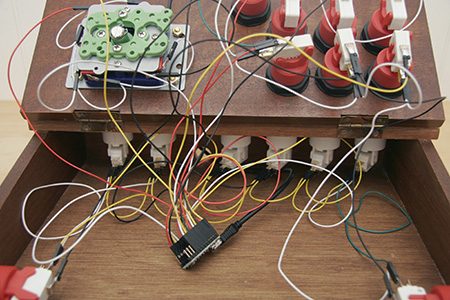
Wiring the Buttons
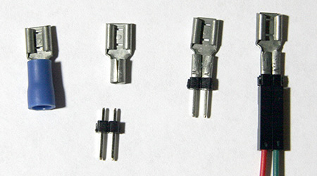
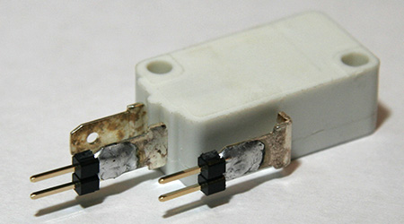
First I thought of a very simple and solderless method to wire up all the buttons. I bought a 100 pack of female .187 solderless terminals and 2 × 40 pin male break away header. I removed the plastic part of terminals and cut up the headers so that I have 2 pin connectors. Both parts can be crimped together with some pliers.
This did work, but sometimes the connection got loose, so I decided to just solder the 2 pin connectors directly to the switches. I have 15 buttons and 1 joystick (4 buttons) and I need 2 of these connectors for each buttons, which means I had to solder 38 connectors.
 |
 |
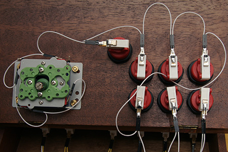
The buttons can be connected to the controller board with dual-female jumper wire. Because I have 2 pins, I can easily daisy chain all button grounds to just a single ground to the controller board.
 |
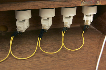 |
I can also daisy chain the triple button B1 and the double button B2 and connect the rest with dual-female jumper wire. I used some 4 pin to 4 × 1 pin cables that allowed me to connect the the buttons in groups of 4 to the controller board.
 |
 |
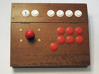
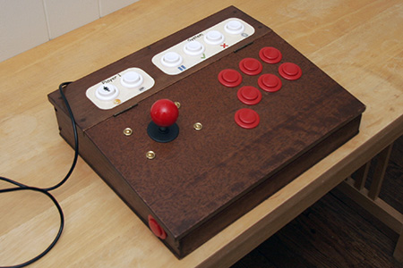
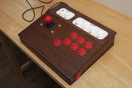
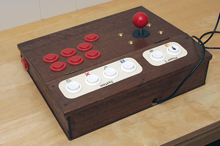
The Finished Controller
 |
 |
 |
 |
Afterthoughts
 |
I learnt a lot. About woodwork, decoupage, PCBs, and electronics. I spent 12 hours and a total of $100 on this controller. I think next time I might just get a X-Arcade Dual for $130... Or maybe not |